24 July 2008

Shutdown the computer remotely

This is will show you how to shutdown a computer (from your own) remotely. there is no need to send a file sneak on their computer or have any contact with them. This requires little or no DOS skills.


step 1Find their computer name
first type "net view"
next find you target in the list (by the way the target needs to be on your network)
congratz you've found your target.

by the way its also easier if u can sneak a peek at their computer for a minute. if you can click start right click my computer click properties then go to computer name. but thats only if theres alot of computers like in an office or a school.


step 2Shutdown -i
go to run and type cmd. this will bring up command promt or DOS. type shutdown -i and a dialog should come up


step 3Type
type the computer name. then change warning time to 2 seconds and type a message if you want.


step 4Done
Click ok and your done

How to enable & disable USB ports


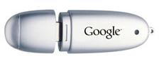
A desktop computer equipped with a CD writer or a DVD burner is a rare sight in most companies. But a much larger security threat is posed by the open USB ports where mischievous office workers can just plugin the Flash Pen Drive, External Hard Disk or their iPod music player and transfer corporate data or even copy licensed software to their memory sticks in seconds.

Also, USB keys are not just a popular way to sneak data out from companies, unhappy employees may use USB ports for delivering trojans or spyware into the company networks.

Now some smart admins disable usb drive by changing the BIOS settings and then lock the BIOS using passwords. Some not so-smart admins fix tapes over the USB ports to prevent employees from inserting any USB device into their computer.

However, both these approaches can prove to be counter-productives as your staff can no longer use USB keyboards, wireless mouse, digital cameras, camcorders, scanners, printers or even USB microphones to their computers.

So a more reasonable option for sysadmins is to disable write access to USB port so that data files cannot be written to the mass storage device. The USB thumb drive will be read-only.

Open the Windows Registry and open the following key
HKEY_LOCAL_MACHINE\System\CurrentControlSet\ Control\StorageDevicePolicies

Now add a new DWORD called WriteProtect and put the value as 0 to disable write privileges to the USB port. To reverse the step, either delete the WriteProtect REG_DWORD or toggle the value to 1 which will enable the port.

Remember that the above trick works only with Windows XP SP2.

If you like to go a step further and disable users from connecting USB storage devices to their computers, here's the trick:

Open registry and navigate to the following registry key:

HKEY_LOCAL_MACHINE\SYSTEM\CurrentControlSet \Services\UsbStor

Now in the right pane, double-click Start and type 4 in the Value data box (Hexadecimal) and quite the registry editor. To enable the USB storage devices, change the Start value back to 3.

No matter how good the protection tricks are, determined people always find workarounds. Here are some of the tricks that may render the above methods unusable:

» Employee may boot computer using a LiveCD like Knoppix or Ubuntu so the USB drives are again available to him for writing.

» They could open the computer chasis, take the battery out to reset the BIOS settings.

» Some may even invest in a PS2 to USB port converter.

» If he manages to get admin access for a temporary period (like installing software), he may undo the registry edits.

The cat-mouse game will never end. USB drives will remain a headache for the sysadmins for some time. However, Windows Vista will make life much simpler for IT administrators. There's a new Policy in Vista that allows USB keyboards or mouse to be used but not any USB devices.

19 July 2008

NASSCOM LIST

NASSCOM
Top 20 IT Software and Service Exporters FY07-08
1 Tata Consultancy Services Ltd.
2 Infosys Technologies Ltd.
3 Wipro Technologies Ltd.
4 Satyam Computer Services Ltd.
5 HCL Technologies Ltd.
6 Tech Mahindra Ltd.
7 Patni Computer Systems Ltd.
8 I-flex Solutions Ltd.
9 Mphasis an EDS company
10 Larsen & Toubro Infotech Ltd.
11 CSC in India
12 Aricent
13 Syntel Inc.
14 Prithvi Information Solutions Ltd.
15 Hexaware Technologies Ltd.
16 Polaris Software Lab Ltd.
17 NIIT Technologies Ltd.
18 Sonata Software Ltd.
19 Mastek Ltd.
20 Genpact India Pvt. Ltd.
Footnote: This list does not include some companies whose corporate headquarters are located
outside India, but have significant India-centric delivery capabilities, and have not shared their Indiacentric
revenue figures. Had they been ranked based on their India revenues, companies such as
Accenture, Cognizant, HP, and IBM and would have also appeared in this ranking.

10 July 2008

Memory Installation

Since it's a lot harder to work on a motherboard when it's sitting inside a case, we might as well install the memory before we slip the mobo into our enclosure. These days, most systems run their memory in dual-channel configurations using pairs of memory modules. Motherboards are typically equipped with four DIMM slots, two of which correspond to each memory channel, so you'll want to check your motherboard's manual to determine which slots correspond to which memory channel. Be sure to install at least one memory module per channel.

Once you've figured out which slots to populate, sliding memory modules into place is a snap. Like processors, modules are keyed so they only fit into DIMM slots one way. Orient your modules accordingly, and apply even pressure along their top edge to seat them into the DIMM slots. If the module rocks back and forth as if on a central pivot point, you've got it turned around the wrong way.

If you're running fancy-pants memory modules with ginormous heat spreaders, like those pictured above, you may run into clearance issues with larger aftermarket processor heatsinks. Unless the heatsink's orientation can be changed to provide additional clearance for the DIMM slots, you'll have to settle for lower profile memory modules or a less extravagant CPU cooler.

When memory modules are seated correctly, retention tabs located at the ends of the DIMM slots should swing up into their upright and locked position, ready for take-off. If these tabs aren't completely locked, you should be able to flick them into place easily with your finger.
Preparing the enclosure
We're done with the motherboard for the moment, and must now prepare the enclosure for its arrival. Time to break out the screwdriver, folks.

The first thing we need to do is remove the enclosure's side panels. With some cases, only the left panel needs to be removed or even can be removed. However, if your enclosure has removable panels on both sides, we recommend taking both off. The additional access will come in handy when we clean up wiring within the case.

Most modern enclosures hold their side panels in place with thumbscrews or mechanical latches, so you probably won't even need a screwdriver to remove them. And if you need instructions on how to use a screwdriver, well, perhaps assembling a system from scratch is a little ambitious.

Removing the case panels gives us access to the enclosure's internals—most importantly, the panel on which the motherboard will set. The motherboard doesn't rest directly on the metal panel, though; that would create all sorts of short circuits. Instead, the motherboard sits atop a series of posts that separate it from the case.

Motherboard posts should come bundled with your case, and they can be screwed directly into the motherboard tray with your bare hands. Making sure they're tight.

When screwing posts into the motherboard, be sure that they line up with the board's mounting holes; posts that don't line up can make contact with solder points on the underside of the board, creating short circuits. We recommend using at least six mounting posts for a standard ATX motherboard, but to be on the safe side, you might as well use as many as there are mounting holes on your board.


Once the posts are in place, fish the I/O shield out of your motherboard box. Most cases already come with a generic I/O shield, but chances are it won't line up properly with your motherboard's port cluster. If your case has a generic shield, pop it out and toss it. The I/O shield that comes with your motherboard should easily snap into place.

Before moving on, we're going to save ourselves some hassle by bending back the metal tabs on the inside of the I/O shield. In the picture above, these tabs can be seen above the PS/2, Ethernet, and Firewire ports. Bending these tabs back will ensure that they don't catch on the motherboard ports when we slide it into the system.

We're now all set up to install the motherboard into the case, but before doing that, it's worth filling in a few other components that will be easier to install in an otherwise empty enclosure.

First among these is our system's hard drive. These days, it seems every case manufacturer mounts hard drives slightly differently, but the enclosure we've busted out today takes a simple approach. Hard drives slide neatly into internal 3.5" bays—with the drive ports facing out, of course—and are held in place by screws. Depending on your enclosure, you may need to secure the drive with screws on both sides; it's a good thing we removed the right-side case panel.

Which internal drive bay ends up housing the system's hard drive is up to you, but I prefer to have drives sitting in lower rather than higher bays. Heat rises, and we might as well put the drive in the coolest part of the case that we can. If you're running a system with multiple hard drives, try not to stack them in bays directly on top of one another. If possible, leave an empty bay between drives to allow air to flow freely between them.

Next up is our system's optical drive. This goes in one of our enclosure's external 5.25" bays, and in traditional cases, it's held in place by screws. Of course, these screws are slightly different from the ones that hold the hard drive in place—you know, because it would be entirely too convenient for the same screw type to be used throughout. All the screws you need should come with the case, and as a rule, ones with finer threads are used to secure optical drives and the motherboard, those with coarser threads and small heads secure hard drives, and those with coarse threads and large heads are reserved for case panels and expansion cards.

If you're going to be running a single optical drive, check to make sure that its jumper is set to Master or Single Drive. This should be the drive's default position, and you don't need to change it unless you plan on running a second optical drive off the same cable. Drives with SATA interfaces are a little more convenient, since they don't have these jumpers and won't need to be configured in this way.

You'll notice that we're installing the optical drive in the case's highest 5.25" drive bay. Optical drives aren't used frequently, so we're not so concerned with whether they're in the coolest possible bay. Instead, I like to mount optical drives as high as possible in tower enclosures to make them easier to reach when the case is sitting on the floor.

If you want to kick it old-school, now would be the time to install a floppy drive in one of the enclosure's external 3.5" bays. Same drill as with the optical drive, except with fewer choices; most cases only have one, maybe two external 3.5" bays. Those inclined to join the 21st century will probably have replaced the aging floppy drive with a zillion-in-one media card reader that slides into the same slot.

Assembling the core

The CPU lies at the core of the modern PC, making it an appropriate place to start our build. For this first step, you'll of course want the processor, and also your system-to-be's motherboard.

This particular assembly guide features an Intel processor with a LGA775 socket, so certain steps won't be applicable to systems using AMD processors based on Socket AM2. Socket AM2 isn't hard to figure out, though; processor installation instructions typically come bundled with both the processor and the motherboard.

After laying the motherboard out on a clean work surface, remove the plastic cover that shields the LGA775 socket's pins from harm. Be careful not to bend or otherwise disturb these pins—they need to line up just right with contact points on the base of the CPU.


With the plastic guard removed, you'll easily be able to unclip the lever that holds the socket's CPU retention mechanism in place. Flip this retention bracket back on its hinges to expose the socket in full.

Modern CPUs are keyed to ensure that they can only be inserted into a socket one way, just like a puzzle piece, so you should have no problem dropping your processor into the socket. LGA775 processors, for example, have little indents along opposing edges that line up with protrusions in the socket. If your CPU struggles to slide smoothly into the socket, chances are you've got it oriented the wrong way.

Once the processor is sitting comfortably in the socket, flip the retention bracket back down and use the lever to clamp it into place. This secures the CPU to the motherboard.

With the processor installed, we can move onto the application of thermal compound. Some folks like to apply thermal paste before dropping the processor into the motherboard, but I find that tends to be a little messier without making things any easier.

Before slathering thermal compound all over our processor's exposed cap, it helps to make sure that cap is nice and clean. Gently brush the cap with a Q-Tip dipped in rubbing alcohol to rid it of any dust or oils that it may have picked up from your grubby carefully manicured fingers during the installation process.


Next, we apply thermal compound. Most retail processors that come packaged with coolers will already have thermal compound applied to the base of the heatsink. If yours does, you can skip this step and proceed directly to heatsink installation. However, we recommend applying thermal compound yourself. Thermal compound works best as a very thin layer between the CPU and heatsink, and most heatsinks that come with paste pre-applied use a thicker layer than is optimal.

You really only need a small dab of thermal compound to ensure complete coverage for the CPU. The dollop pictured above is more than enough, and it's best squeezed onto the center of the processor's metal cap.


Next, spread the thermal compound over the processor, ensuring complete and even coverage. Some thermal compounds come with plastic spreaders, but you can also use a credit card or even a finger wrapped in a plastic bag. What you want to end up with here is a relatively smooth layer that's just thick enough to completely cover the processor.

Don't worry about getting a little paste on the CPU retention bracket; it won't do any harm there. You will want to clean up any compound that makes its way onto the motherboard or its surface-mounted components, though. A Q-Tip dipped in rubbing alcohol should do the trick.

Once the processor is glazed with compound, we can turn our attention to the heatsink. If you've elected to do your own thermal compound application, you'll want to make sure that the heatsink's base is scrubbed clean. Rubbing alcohol usually gets the job done, but some heatsinks are slathered with particularly gooey, clingy, or otherwise uncooperative thermal interface materials. It may be necessary to break out more noxious substances, such as nail polish remover, to restore the base of the heatsink to a bare metal shine.

Be careful not to mar the base of the heatsink when removing any thermal compound that may cover it. Some heatsinks need to be scraped clean of thermal compound, and it's best to scrape with something plastic rather than a metal tool that will gouge the heatsink's surface.


With our system's processor blanketed by a thin veil of thermal compound and our heatsink's base scrubbed clean, it's time to mate the two together. Before dropping the heatsink into place, ensure that all four of the heatsink's plastic retention posts are rotated clockwise into their installation position. Next, place the heatsink on top of the CPU, lining up the four retention posts with corresponding holes in the motherboard.

When the posts are lined up, depress the black plastic tabs one by one to lock the heatsink into place. You should hear an audible click as each post locks into place.

Since the area around a modern motherboard's CPU socket is often crowded with tall capacitors, heatsinks, and elaborate heatpipe arrays, I find it's best to depress the retention post that's least accessible first. The post directly opposite that one should be next, followed by the remaining two in whichever order you desire.


After locking the heatsink into place, plug its fan into the appropriate header on the motherboard. The CPU fan header is usually right next to the socket, but if you can't find it, your motherboard manual should have a map highlighting its location.

Note whether the heatsink you're using features a fan with a three- or four-pin header. That information will come in handy when we jump into the BIOS to configure fan speed control, since some motherboards can't auto-detect fan types.

How to build a PC

A step-by-step guide to enthusiast system assembly
The best thing about being a PC enthusiast—beyond, of course, the never ending joy of serving as the personal support technician for friends and family—is being able to assemble a system from the ground up with the perfect mix of components for a given budget. That mix of components will vary depending on your needs, but with today's market so rich with high-performance hardware at affordable prices, it's easy to spec a custom system that will blow the doors off pre-built boxes from major PC vendors.

Users new to building systems from scratch need more than just a shopping list, though. There's an art to assembling a rig from bare components. Building a PC can be a daunting task for a newbie who has never put a system together before. For those folks, a step-by-step guide covering the basics of system assembly is given below. Keep reading to know how to build a PC from scratch.

Getting started
Before diving into assembly, you'll want to gather a few supplies and find a large, clean work area that preferably isn't teeming with static electricity. As far as tools are concerned, you shouldn't need more than a Philips head screwdriver; one that holds screws in place with a magnetic tip is ideal. We'll also be using rubbing alcohol, Q-Tips, and zip ties. Everything else that you need should be included with the various components you've gathered to put into the system. Yes, you'll need those components, too.

Prior to removing any of the components from their packaging, you'll want to take the precaution of grounding yourself by touching a large, metal object like a table base, filing cabinet, or your PC's case—whatever's nearby—in order to discharge any static electricity you may be carrying with you. Static electricity can be harmful to PC components. Some folks prefer to use an anti-static wristband in order to keep themselves grounded.

08 July 2008

Sony Ericsson Naming Explained


Thanks to whoever added some detailed Sony Ericsson naming info on Wikipedia. Just as the last two letter of BMW models indicate the vehicle’s displacement, there’s a story behind each Sony Ericsson name.
The most common format uses a total of five (or six) characters, eg. K750i. This format begins with a capital letter to denote the series of the phone (K750i). This is then followed by three numbers (K750i).

The first number indicates the sub-series of the phone, the second indicates the amount of progression from the previous release, i.e. K700i to K750i, and the third number is always either a ‘0′ or ‘8′ and the letter ‘8′ is used either to show a variation of the phone destined for a different market without a feature , or it is used to separate phones which have identical specifications but the designs are different. Examples:

* The W888 is a W880i without 3G
* The K610i and K618i.

Finally, the lowercase letter at the end of the model name describes the market for which a product is intended; these are:

* a for the Americas,
* c for China,
* i for an international version

There is also an ‘im’ suffix used for branding i-mode phones. Often the last letter is left out to describe the phone generically with no region specific branding.
 

©2009 Edifying Minds | by TNB